ZBasic Language Reference
219
ZBasic Microcontrollers
Appendix M - External Components for Generic Target Devices
The circuits described below represent the minimum external circuitry required to operate a generic target
device. The requirements vary depending on the device, e.g. some generic target devices have on-board
serial hardware (i.e. a UART), on-board analog-to-digital-converter, etc. and some don’t.
Power Source
The AVR chip needs a regulated voltage source capable of providing current to both the AVR and
surrounding circuitry. See the datasheet for the particular target device for the minimum and maximum
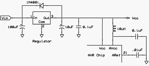
acceptable operating voltages. A stylized power supply circuit is shown below. Note that a particular
AVR devices may not have an AVcc or ARef pin. Generally, a suitable heatsink will be required in most
cases to keep the regulator IC below its maximum operating temperature. Consult the regulator
datasheet for more information.
Power Supply Circuit
If the target AVR does not have analog circuitry (analog-to-digital converter and/or analog comparator) it
will not have an AVcc or Aref pin. Some AVR devices do not have an Aref pin even though they have
analog circuitry. If it does have an AVcc pin but you do not plan to use the on-board analog elements you
can eliminate the components shown connected to AVcc and Aref. In this case, AVcc would be
connected to Vcc and Aref can be left unconnected. Although not shown on this diagram, the AVR chips
have one or more ground pins, all of which must be connected to the common ground of the system.
Clock Source
The AVR chip requires a clock source running at a frequency suitable for your application (denoted as
F_CPU in the generic target parameters, see section 5.3). Most AVR chips have internal oscillators that
can be used in some applications. However, the internal oscillator frequency may not be accurate
enough or stable enough (over the operating temperature range) to meet the requirements of your
application. Generally speaking, the internal oscillator is not accurate enough to support reliable serial
communication where the baud rate must be within 2% or less of the desired rate for reliable
communication.
If the AVR supports it, the best way to provide the required clock source is to connect a crystal of the
desired resonant frequency to the Xtal1 and Xtal2 pins along with the necessary load capacitors (the
value of which depends on the crystal specifications) as shown in the circuit diagram below.
Another option is to feed an externally generated clock signal into one of the Xtal pins (check the data
sheet for the correct pin).