ZBasic Language Reference
212
ZBasic Microcontrollers
Clock Source
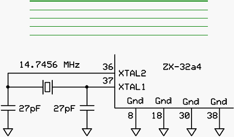
The ZX-32a4n and ZX-128a4u devices require a clock source running at 14.7456MHz. The easiest way
to provide this clock source is to connect a crystal of that frequency to pins 36 and 37 along with the
necessary capacitors. Some recommended crystals are shown in the table below.
Recommended Crystals
Package
Crystal
HC-49/US
ECS-147.4-20-4X (Digi-Key #X1102-ND)
HC-49/U
ECS-147.4-20-1X (Digi-Key #X1032-ND)
Cylinder
ECS-147.4-18-9X (Digi-Key #XC-1382-ND)
ZX-32a4 and ZX-128a4u Clock Source
If you already have a clock source at the required frequency you can feed that signal directly to pin 37. In
this case there would be no connection to pin 36.
Serial Interface
The ZX-32a4 and ZX-128a4u devices require a serial interface for downloading code into Program
Memory and for your program’s use via Com1. The recommended serial interface circuitry is shown
below. This circuit has two sub components. The MAX3232E chip functions as an RS-232 level
converter that translates the 0-3.3 volt signals of the chip to the standard RS-232 voltage levels.
The second component is the ATN circuitry that is used to signal the chip to go into download mode. The
latter circuitry is that portion connected between pin 4 of the DB-9 serial connector and pin 35 of the chip.
You may want to include a jumper in the ATN circuitry so that it can be disconnected when downloads are
not required. With the ATN circuitry connected, the device will receive a reset pulse on every positive
transition of pin 4 (DTR) of the serial connector. If alternate component values are chosen you must
ensure that the chip receives a reset pulse of at least 2uS on every positive transition of the DTR signal
on pin 4 of the serial connector.
One advantage to using this recommended circuit is that the MAX3232E chip includes a DC-DC
converter that produces nominally +/- 10V from a 3.3 volt source. This is particularly useful if your
application requires one or more of these voltages. For example, some LCD devices require a low-
current negative supply for their backlight circuitry. The positive voltage is available on pin 2 of the
MAX3232E while the negative voltage is available on pin 6. Consult the datasheet for the MAX3232E
device for information on the current capacity of these supplies.
The PDI_DATA pin of the chip (pin 34) is used for factory programming and should be left unconnected.