ZBasic Language Reference
199
ZBasic Microcontrollers
Appendix H - ZX-1280 Series Hardware Reference
The ZX-1280 series devices utilize the 100-pin TQFP package version of the Atmel AVR ATmega1280
microcontroller that has been programmed with the ZX control firmware. In order to use the ZX-1280 or
ZX-1280n you must add several additional components as described below. In each of the diagrams
presented below, only a portion of the ZX pins is shown. Those that are not germane to the circuit being
discussed are omitted for clarity.
H.1 ZX-1280 Series Specifications
The electrical specifications of the ZX-1280 series devices are exactly those of the ATmega1280. Rather
than reproducing them here the reader is directed to the datasheet published by Atmel. It can be
obtained from the Atmel website |http://www.atmel.com or from the ZBasic website |http://www.zbasic.net.
H.2 ZX-1280 Series Required External Components
The circuits described below represent the minimum external circuitry required to operate the ZX-1280 or
ZX-1280n. Depending on your application, you may need additional circuitry to take advantage of the
capabilities of the ZX-1280 series device. In contrast to some other ZX devices, the ZX-1280 series does
not require an external EEPROM for program storage. Rather, the compiled user program is stored in the
ZX’s internal Flash memory. The maximum user program size is 60K bytes for the ZX-1280 and 124K for
the ZX-1280n.
Power Source
The ZX-1280 series devices need a regulated voltage source capable of providing at least 200mA of
current. The voltage typically used is 5 volts but the ZX-1280 will operate between 4.5 volts and 5.5 volts.
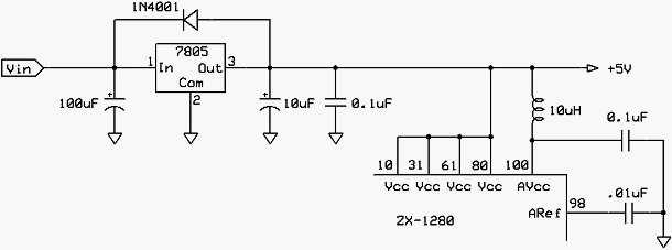
A recommended circuit is shown below. A suitable heatsink will probably be required in most cases to
keep the regulator IC below its maximum operating temperature. Consult the regulator datasheet for
more information.
ZX-1280 Series Power Source
If you do not plan to use the Analog-to-Digital converter channels you can eliminate the inductor and the
two capacitors on the right side of the diagram. In this case, pin 64 would be connected directly to the
power source (same as pin 21, etc.) and pin 62 can be left open. Although not shown on this diagram,
the ground pins of the ZX-1280 (pins 11, 32, 62, 81 and 99) must be connected to the common ground of
the system.