ZBasic Language Reference
185
ZBasic Microcontrollers
ZX-40 Series Program Memory (VM models only)
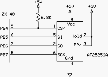
With firmware versions v1.1 and later, the Atmel 25HP512 (Digi-Key #AT25HP512-10PI2.7-ND) can also
be used for applications that require larger EEPROM space. The electrical connections for this device
are identical to those shown above. However, since this device has different characteristics than the
AT25256A, special configuration is required. See Section 11.2 for more information.
Serial Interface
The ZX-40 series devices require a serial interface for downloading code into Program Memory,
performing field updates of the control program, and for your program’s use via Com1. The
recommended serial interface circuitry is shown below. This circuit has two sub components. The
MAX232 chip functions as an RS-232 level converter that translates the 0-5 volt signals of the ZX to the
standard RS-232 voltage levels.
The second component is the ATN circuitry that is used to signal the ZX to go into download mode. The
latter circuitry is that portion connected between pin 4 of the DB-9 serial connector and pin 9 of the ZX.
You may want to include a jumper in the ATN circuitry so that it can be disconnected when downloads are
not required. With the ATN circuitry connected, the ZX will receive a reset pulse on every positive
transition of pin 4 (DTR) of the serial connector. If alternate component values are chosen you must
ensure that the ZX receives a reset pulse of at least 2uS on every positive transition of the DTR signal on
pin 4 of the serial connector.
One advantage to using this recommended circuit is that the MAX232 chip includes a DC-DC converter
that produces nominally +/- 12V from the 5 volt source. This is particularly useful if your application
requires one or more of these voltages. For example, some LCD devices require a low-current negative
supply for their backlight circuitry. The positive voltage is available on pin 2 of the MAX232 while the
negative voltage is available on pin 6. Consult the datasheet for the MAX232 device for information on
the current capacity of these supplies.
The schematics below contain several references to +5V. For ZX-40 series devices that can operate at a
lower voltage, e.g. 3.3V, these references should be to the actual operating voltage.