ZBasic Language Reference
165
ZBasic Microcontrollers
11.1.1 Emergency Update Procedure
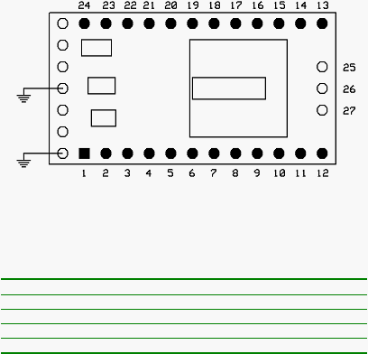
To prepare a 24-pin VM mode ZX device for an emergency firmware update you must ground the center
terminal and the bottom terminal on the left end of the ZX device as shown in the diagram below. This
can usually be done with a temporary connection like a test wire with alligator clips or similar connectors.
When the ZX is powered up with these connections it enters the emergency update mode instead of
operating normally.
Finally, the zload command must be invoked in emergency update mode, an example of which is shown
below.
zload –c2 –e zvm_1-12-0.zvm
When the emergency update completes successfully the ZX may be powered off and the grounding
jumpers may be removed. When it is powered up again it will begin running the newly installed control
program normally. Note that the emergency mode may be used any time but because of the extra
connections that are required it is primarily intended for extraordinary circumstances when the normal
update mode cannot be employed.
24-pin ZX Device Connections for Emergency Update Mode
The emergency update procedure for other ZX devices is similar to that described above. To prepare for
the emergency firmware update, consult the table below for the specific device and ground the indicated
pin or pins.
Device
Pins to Ground
ZX-40, ZX-40a, ZX-40p, ZX-40s
5, 7 (B.4, B.6)
ZX-44, ZX-44a, ZX-44p, ZX-44s
2, 44 (B.4, B.6)
ZX-1281
25 (D.0)
ZX-1280
43 (D.0)
When the ZX powers up and detects that these pins are grounded, it will enter the emergency update
mode and await an emergency firmware download on the serial port. After the firmware update is
downloaded using the zload command with the –e option the device should be powered off and the
grounding jumpers should be removed. When it is powered up again it will begin running the newly
installed control program normally.
11.2 Device Configuration
The device configuration option, -z, can be used to set configuration parameters of the device (held in the
reserved system Persistent Memory). The supported elements are given in the table below.